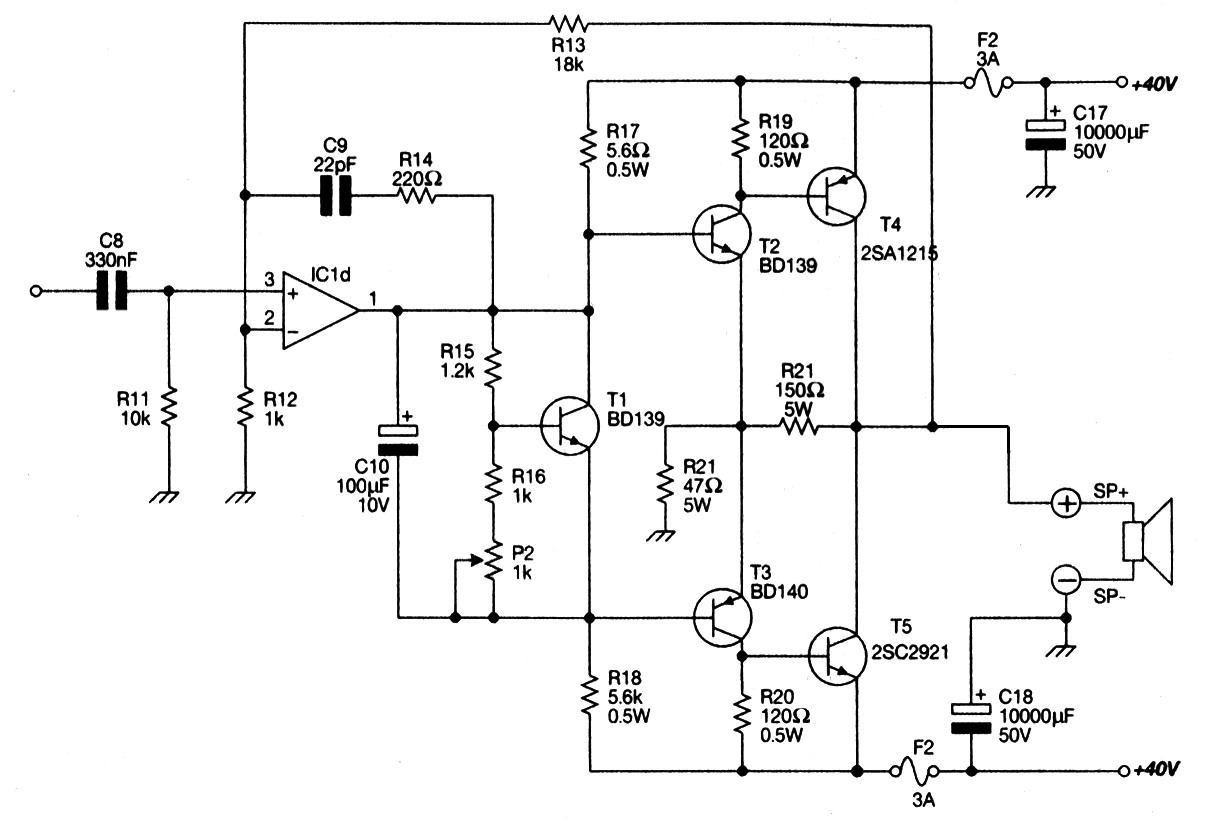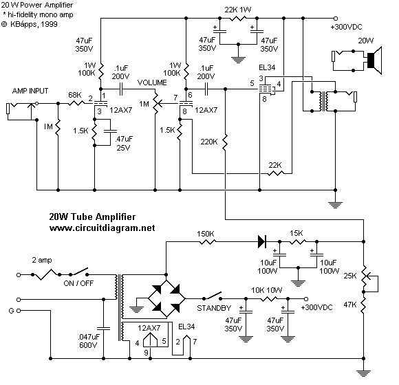

But you can find lots of stuff on the web, fortunately. Altronics had a Mosfet amplifier module which produced 200W into a 4 Ohm load and so we decided to take a look it. The first release of the miniHFPA HF Packer Amp (R1) is a new design physically but has its roots from the HFPackerAmp V4 R6 This push-pull amplifier uses a voltage follower and MOSFET biasing. hf power amplifier Hi, I would like to design an HF power amplifier but all the schematics i have found are not in the desired bandwith !! SPecifications of the amplifier: Input signal : 0 to 12V between 800Khz and 5Mhz OUtput signal: 0 to 12V but 60W !!! I would like tu use a PUSH PULL Model: HF Linear Amplifier BJ-200 - Baojie Electronics Co. ! DC supply voltage 45w HF Mosfet Amplifier with Controller. It should also be used on the ring terminal used to hold Diode D2. LED-IN, LED-FAN, ТХ indicators are on PA front panel.
#Power amp circuit schematic driver
The arrangement is in a source follower configuration with an n-channel, and p-channel type forming a complimentary symmetrical push-pull driver stage. Examples would be Sub-woofer amp, FOH stage amplifier, One channel of a very high-powered surround sound amplifier etc. This Hi-Fi amplifier circuit is suitable for a lot applications like general Shop order. IF not, I would like to have an electrical engineer design one with two of these mosfets and also with one mosfet.

PA circuit using a MOSFET and a more detailed schematic diagram of a MOSFET, showing the parasitic elements. The amplifier uses four Motorola MRF150 50 volt TMOS power FETs configured in push-pull/parallel and biased for class AB linear operation. Current Id should be less than that can be A600 v2. Here the schematic diagram of 800 watt audio power amplifier with MOSFET for final amplification. This circuit utilizes the ‘‘m-amp’’ technique to achieve very high voltage gain.

The drain-to-source supply is ð ì VD, and each stage’s current is adjusted with the gate bias adjustment to 150 mA. The PCB pattern closely follows the schematic diagram.I tested with couple of them including A SMT Dual Gate MOSFET Preamplifier for 50 MHz. This has the advantage of stunningly low Rds and hence high efficiency, but does nothing for HF MOSFET amplifier with soft clipping: The HF section consists of a 110W Power MOSFET amplifier with special lateral MOSFETS, the almost ideally complementary N-channel 2SK135 and P-channel 2 SJ 50, once manufactured by Hitachi. We can use MOSFETs to make digital devices such as logic gates (AND, OR, NOR, etc. This compact little amplifier is the brain-child of Pat Murdoch, ZL1AXB, in Auckland, New Zealand. Description: This is a continuation of articles by William Sabin. The Op amp output potential will be just right to ensure that Vout = Vin. Part numbers in parentheses are Mouser (Mouser Electronics, 968 N Main St, Mansfield, TX 76063 tel 80, 81, fax 81 sales HF PACKER AMP V4R6 part of the amplifier module while the filter board is mounted above the amplifier module. 50 Watts Mosfet Amplifier A PL519 HF Power Amplifier. With 45-48V – the power decreased up 600 Watt HF Amplifier Schematics plans by K9GDT and all infos to build a 600 Watt HF Amplifier.


 0 kommentar(er)
